Smart Knee Brace (The PT-Squared)
Introduction
In February 2025, my friends and I entered the ASBME Make-A-Thon, an annual competition held at USC where 12-15 teams are given one weekend to design, build, and pitch a biomedical engineering product. That year, teams were tasked with designing a device for knee injury prevention, with applications to physical therapy. Our team spent the weekend brainstorming and iterating on our design under strict time constraints.
I was in charge of the electrical and software side, which involved selecting sensors and electrical components, wiring them with a microcontroller, and writing the code to make everything function correctly. I also worked closely with my teammates to ensure that my work fit into the overall system.

Our Problem: Patellar Tendonitis (PT)
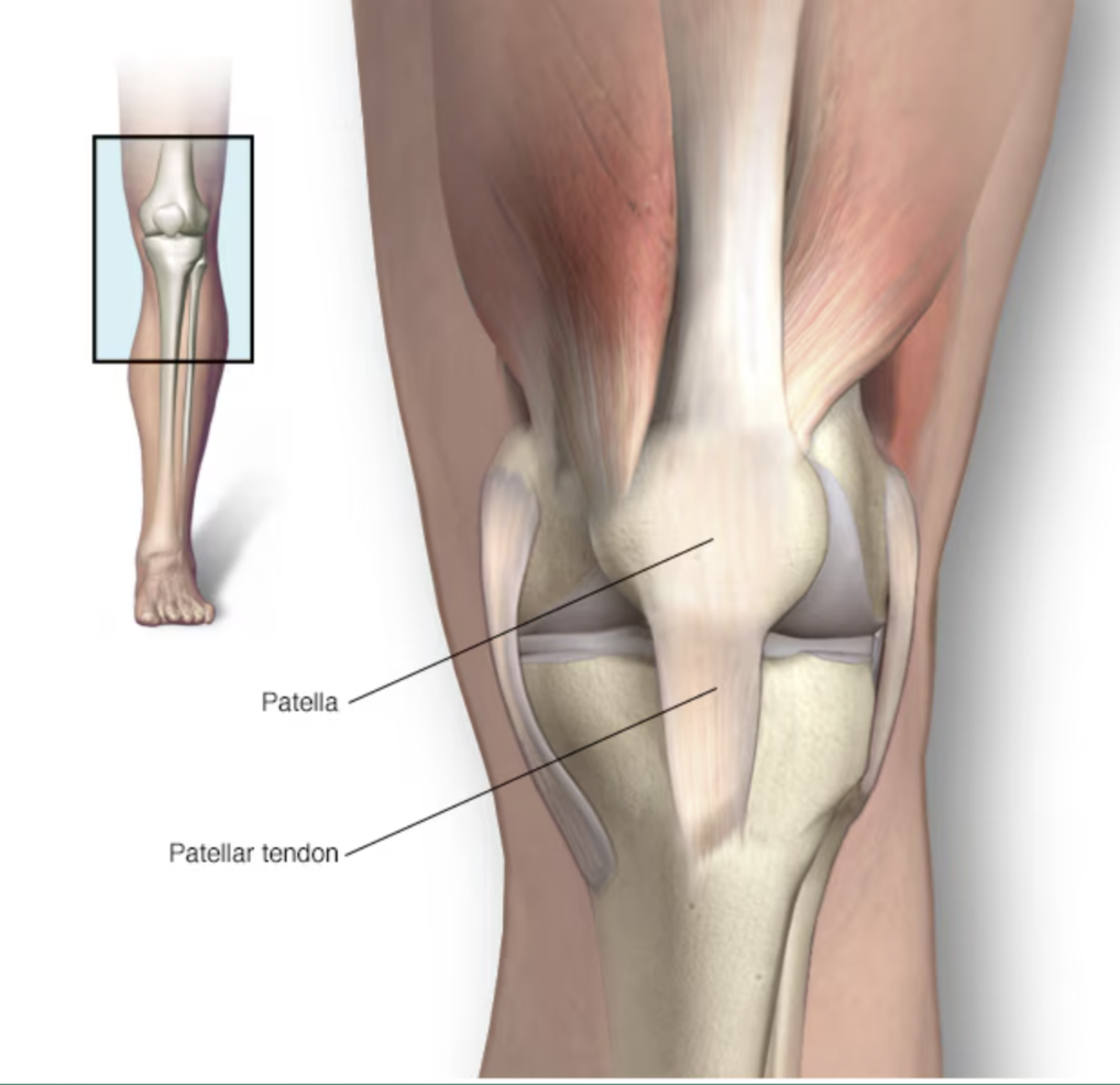
What is it?
PT is an injury to the tendon connecting the kneecap to the shinbone.
What causes it?
Overuse from repeated stress on the patellar tendon.
Who is at risk?
PT is common in athletes ages 15-30 who jump (basketball, volleyball), but anyone can get it.
Why is it important?
The patellar tendon helps with kicking, running, and jumping—hence the name "Jumper's Knee."
Design Goals & Constraints
Design Goals
- Alert the user when PT injury is at risk.
- Provide the user with vibration therapy on PT.
- Comfortable and cost-effective design.
Constraints
- Given a variety of electronics, inputs, and outputs.
- CAD and 3D-Printing allowed.
- 48 hours to complete the product.
Initial Design
Physical therapy patients recovering from Patellar Tendonitis injuries typically perform squats to strengthen the tendon. Unfortunately, it is easy for them to reinjure themselves with bad form.
We decided to create a smart knee brace that alerts the user of poor squat form and applies vibration therapy to the tendon. The idea was to take an old knee brace, attach two 3D-printed parts to the left/right sides, and mount the electronics on them.
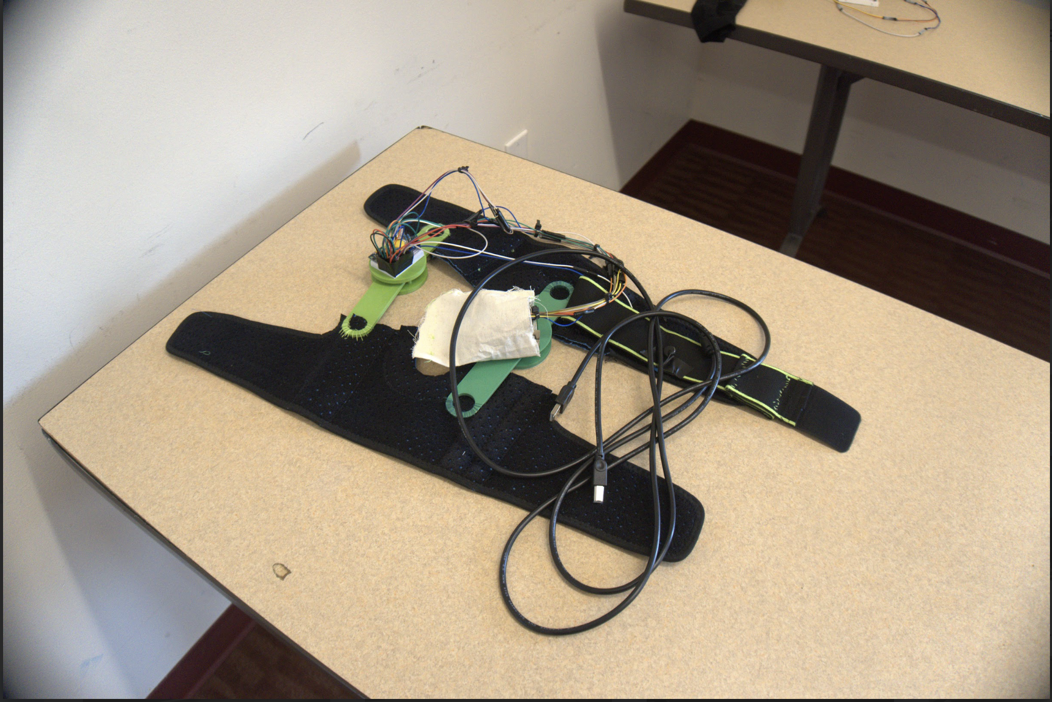
Mechanical Design
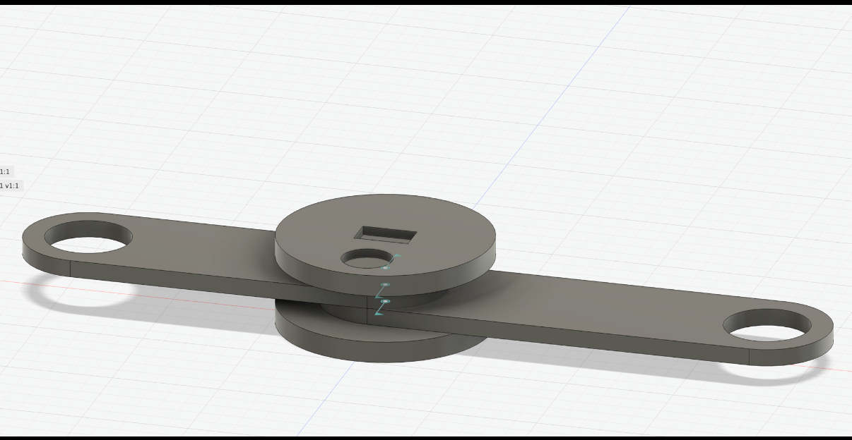
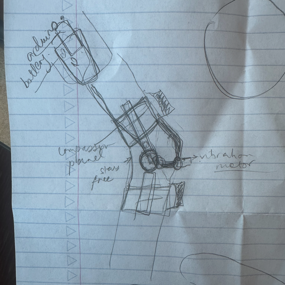
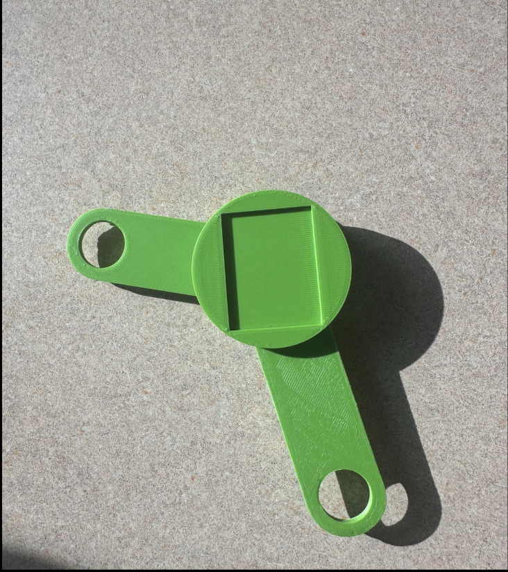
My teammates designed a brace attachment in Fusion 360 to give the brace more physical functionality. The two rectangular ends have holes that attach to the brace, and can rotate so that the user is able to bend their knee. They are sandwiched between two plates, and the top one has an extruded cut for a small breadboard to fit inside. The image above was our first iteration, and after printing it we realized that the extruded cut was too small. The final print is shown to the right.
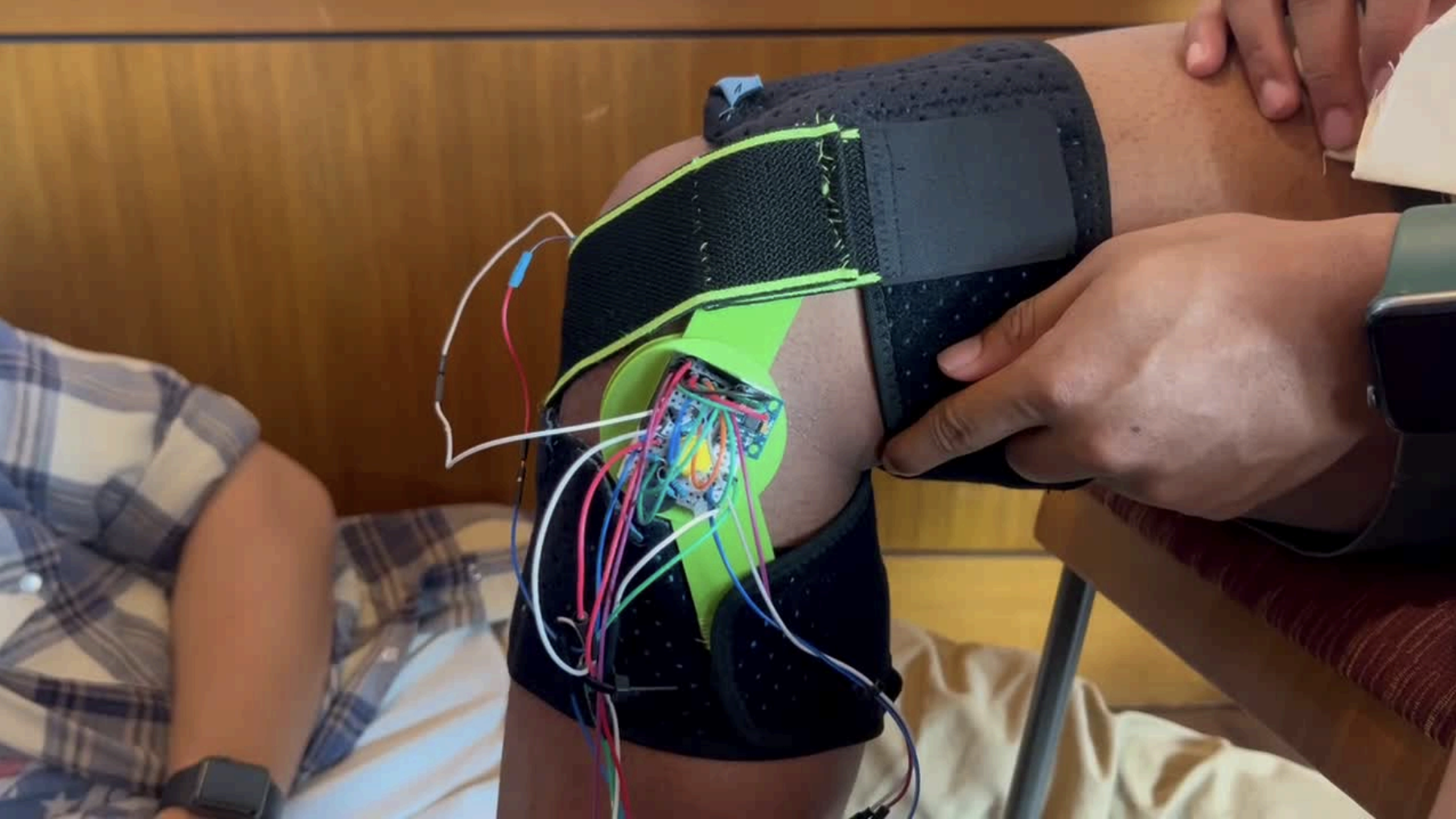
Electronics
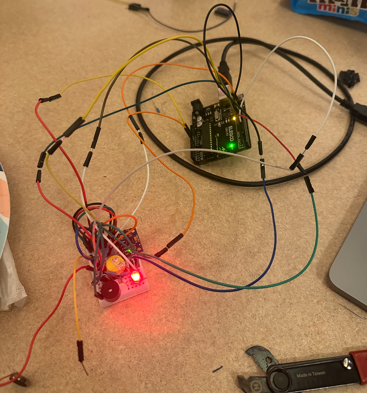
Circuit before wire management.
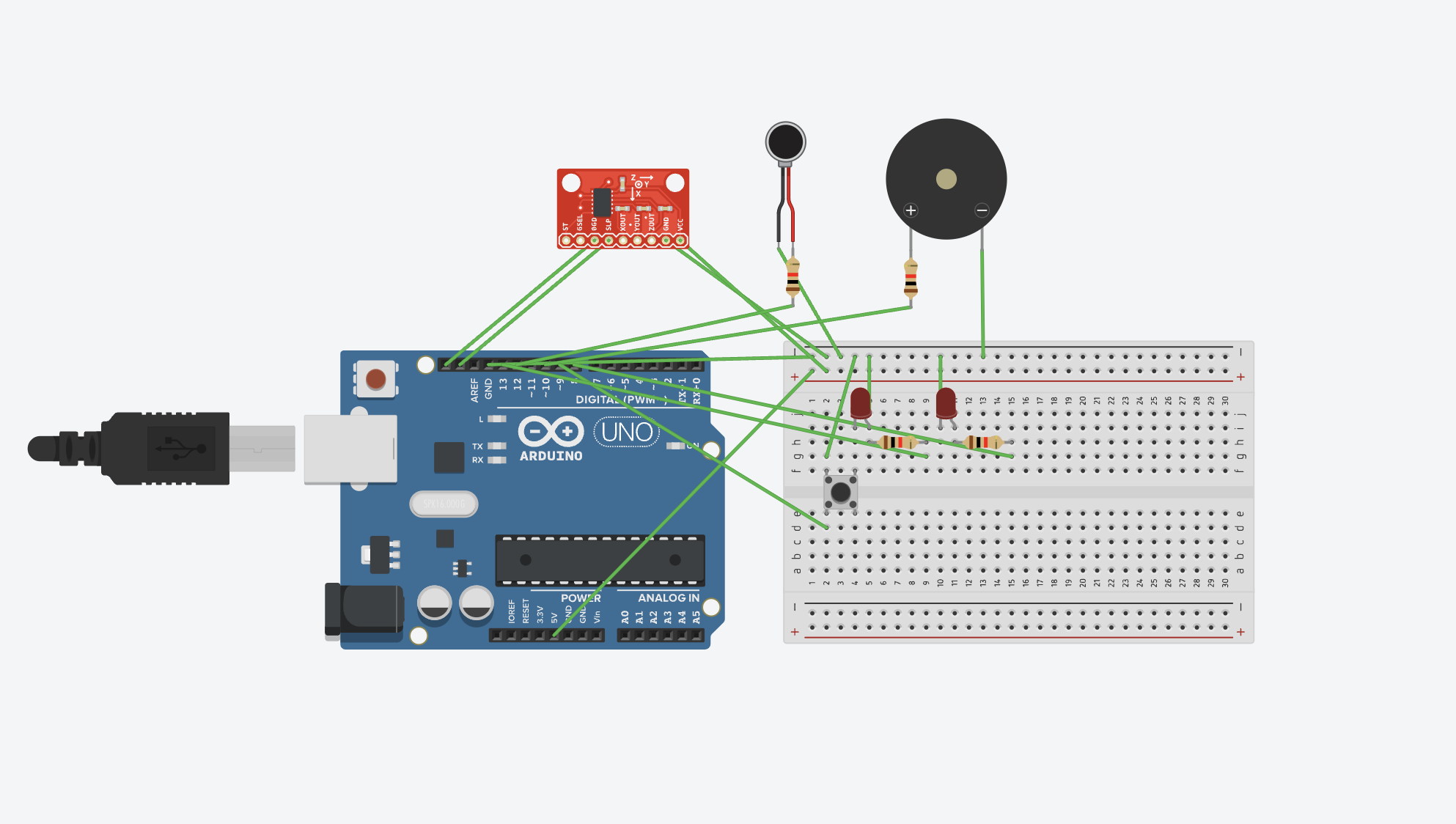
For the electronics, I used an Arduino Uno and several inputs/outputs. In order for the brace to detect poor squat form, I chose an MPU6050 accelerometer, which was placed on the side of the brace to measure the X-Z angle during a squat. In other words, if the user’s knees caved in, the accelerometer would tilt farther to the left, causing the angle measured to be greater. When this threshold is crossed, a piezo buzzer beeps. To provide the user with vibration therapy, I soldered on a 3V vibration motor. Although this is a digital output, there is an Arduino library that uses PWM to allow the motor to operate at more than two strengths. I also wired two buttons and an LED so that the user can easily switch between both modes.
Software
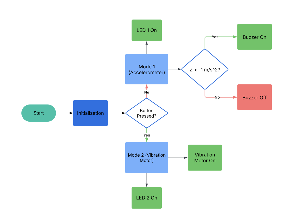
Below is the Arduino code I wrote for this project along with a flow chart.
            #include
              #include
              #include
              #include

              #define BUZZER_PIN 12
              #define BUTTON_PIN 13
              #define LED1_PIN 10
              #define LED2_PIN 8
              const float CAVING_IN = -4;
              const int motorPin = 11;

              VibrationMotor myVibrationMotor(motorPin);

              Adafruit_MPU6050 mpu;
              bool mode = false;
              bool lastButtonState = HIGH;
              bool buttonState = HIGH;

              void setup() {
                Serial.begin(115200);
                while (!Serial) delay(10);

                Serial.println("Adafruit MPU6050 test!");

                if (!mpu.begin()) {
                  Serial.println("Failed to find MPU6050 chip");
                  while (1) delay(10);
                }
                Serial.println("MPU6050 Found!");


                mpu.setAccelerometerRange(MPU6050_RANGE_8_G);
                mpu.setGyroRange(MPU6050_RANGE_500_DEG);
                mpu.setFilterBandwidth(MPU6050_BAND_21_HZ);
                pinMode(BUZZER_PIN, OUTPUT);
                digitalWrite(BUZZER_PIN, LOW);

                pinMode(LED1_PIN, OUTPUT);
                pinMode(LED2_PIN, OUTPUT);
                pinMode(BUTTON_PIN, INPUT_PULLUP);

                digitalWrite(LED1_PIN, HIGH);
                digitalWrite(LED2_PIN, LOW);


                Serial.println("\nReading accelerometer and gyroscope data...\n");
              }

              void loop() {
                int intensity = 255;
                  buttonState = digitalRead(BUTTON_PIN);

                // Detect button press (falling edge detection)
                if (buttonState == LOW && lastButtonState == HIGH) {
                  mode = !mode;  // Toggle mode

                  if (mode) {
                    // Mode 2: Accelerometer OFF
                    digitalWrite(LED1_PIN, LOW);
                    digitalWrite(LED2_PIN, HIGH);
                    noTone(BUZZER_PIN); // Stop buzzer
                    Serial.println("Mode 2: Accelerometer OFF");
                    myVibrationMotor.on(intensity);
                    // delay(2500);
                    // myVibrationMotor.off();
                  } else {
                    // Mode 1: Accelerometer ON
                    myVibrationMotor.off();
                    digitalWrite(LED1_PIN, HIGH);
                    digitalWrite(LED2_PIN, LOW);
                    Serial.println("Mode 1: Accelerometer ON");
                  }

                  delay(200);  // Debounce delay
                }

                lastButtonState = buttonState;

                // Only run accelerometer logic in Mode 1
                if (!mode) {
                  sensors_event_t a, g, temp;
                  mpu.getEvent(&a, &g, &temp);

                  // Detect knees caving in
                  bool buzzing = false;
                  if (a.acceleration.z < CAVING_IN) {
                    Serial.println("Knees Caving In!");
                    buzzing = true;
                  }

                  // Control buzzer
                  if (buzzing) {
                    tone(BUZZER_PIN, 1000);
                  } else {
                    noTone(BUZZER_PIN);
                  }

                  // Print accelerometer data
                  Serial.print("Acceleration X: ");
                  Serial.print(a.acceleration.x, 2);
                  Serial.print(" m/s^2, Y: ");
                  Serial.print(a.acceleration.y, 2);
                  Serial.print(" m/s^2, Z: ");
                  Serial.print(a.acceleration.z, 2);
                  Serial.println(" m/s^2");

                  Serial.println("-------------------------------");
                }

                delay(500);
              }
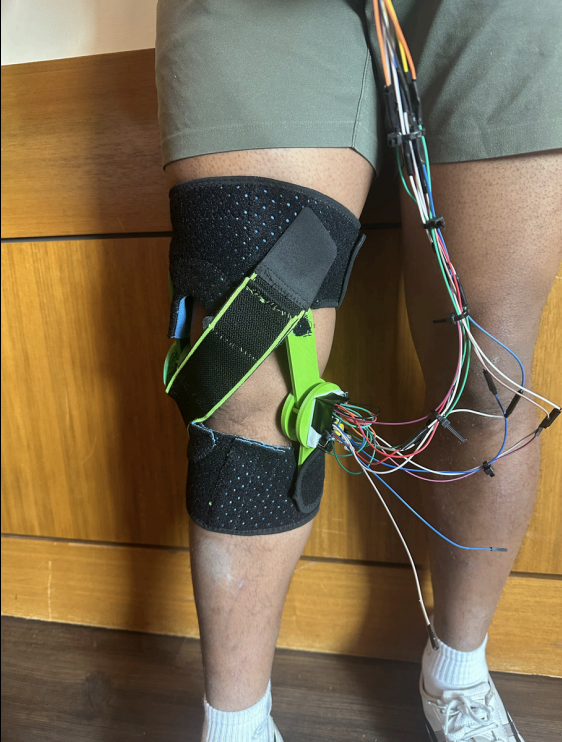
Final Design & Demonstration
Below are demos of both modes. The idea is that the user can improve their squat form during physical therapy, then turn on the vibration motor during the car ride home.
Results
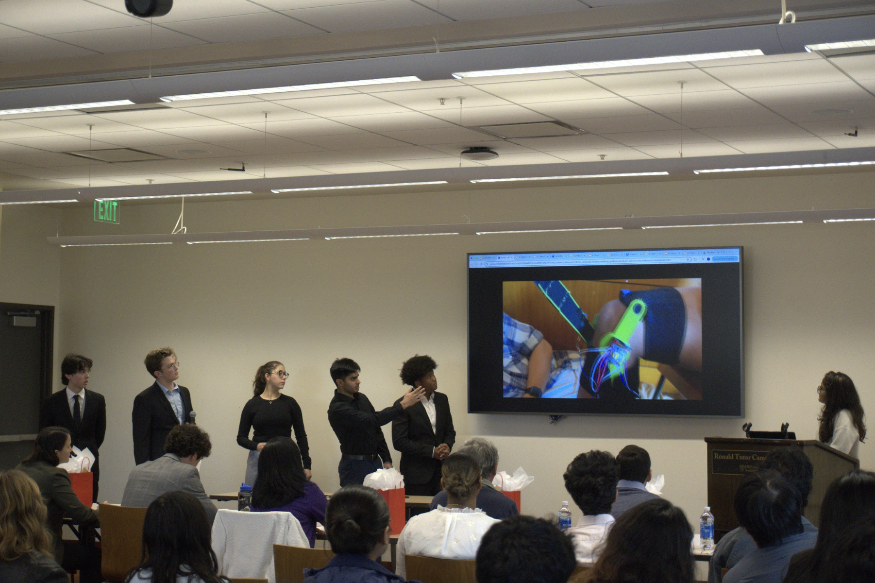
We won second place!
At the end of the Make-A-Thon, we pitched our product to 12 judges, who were professionals in the biomedical device and physical therapy industries. Our team won second place and we were awarded $600 for our efforts!