Electric Guitar
Introduction
For a linear circuits class, I was given the last month of the semester to design and construct an electric guitar. This project reinforced concepts learned in the course, such as RC filters, operational amplifiers, PCB design, and using EE lab equipment for testing.
Electrical Design: Twin-T Notch Filter
An electric guitar makes sounds by converting string vibrations into electrical signals. However, there is often interference between these signals, such as unwanted frequencies or noise. For this reason, I had to use a filter to suppress the G string (196 Hz) while letting the other strings pass through.
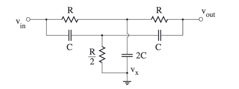
I used a passive twin-T bandstop (notch) filters, as shown to the left. This has a gain function:
$$ \frac{V_{\text{out}}}{V_{\text{in}}} = \frac{K(s^2 + \omega_o^2)}{s^2 + \frac{s \omega_o}{Q} + \omega_o^2} $$
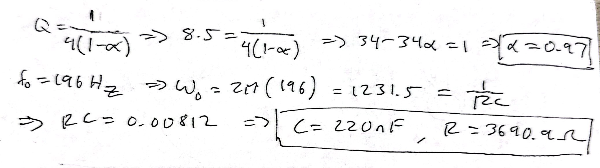
I was required to design it so that \( Q = 8 \) and \( f = 196 \mathrm{Hz} \). Additionally, I ensured that the feedback factor, \( \alpha \), was less than 1 so that the notch is stable and narrows at the target frequency.
After some calculations, I chose R = 3690 \(\Omega \) and C = 220 \(\mathrm{nF} \).
LTspice Simulation
In the final circuit design, I added three op amps, which serve different purposes. U1 is a unity-gain buffer, which isolates the filter output. U2 takes the output from U1, scales it using a voltage divider (RQ1 and RQ2), and feeds it back into the filter, ensuring that \( \alpha = \frac{RQ1}{RQ1 + RQ2} \) is less than 1. U3 is a non-inverting op amp that amplifies the supply voltage by a factor of 11, since its gain is \( 1 + \frac{R6}{R5} \).
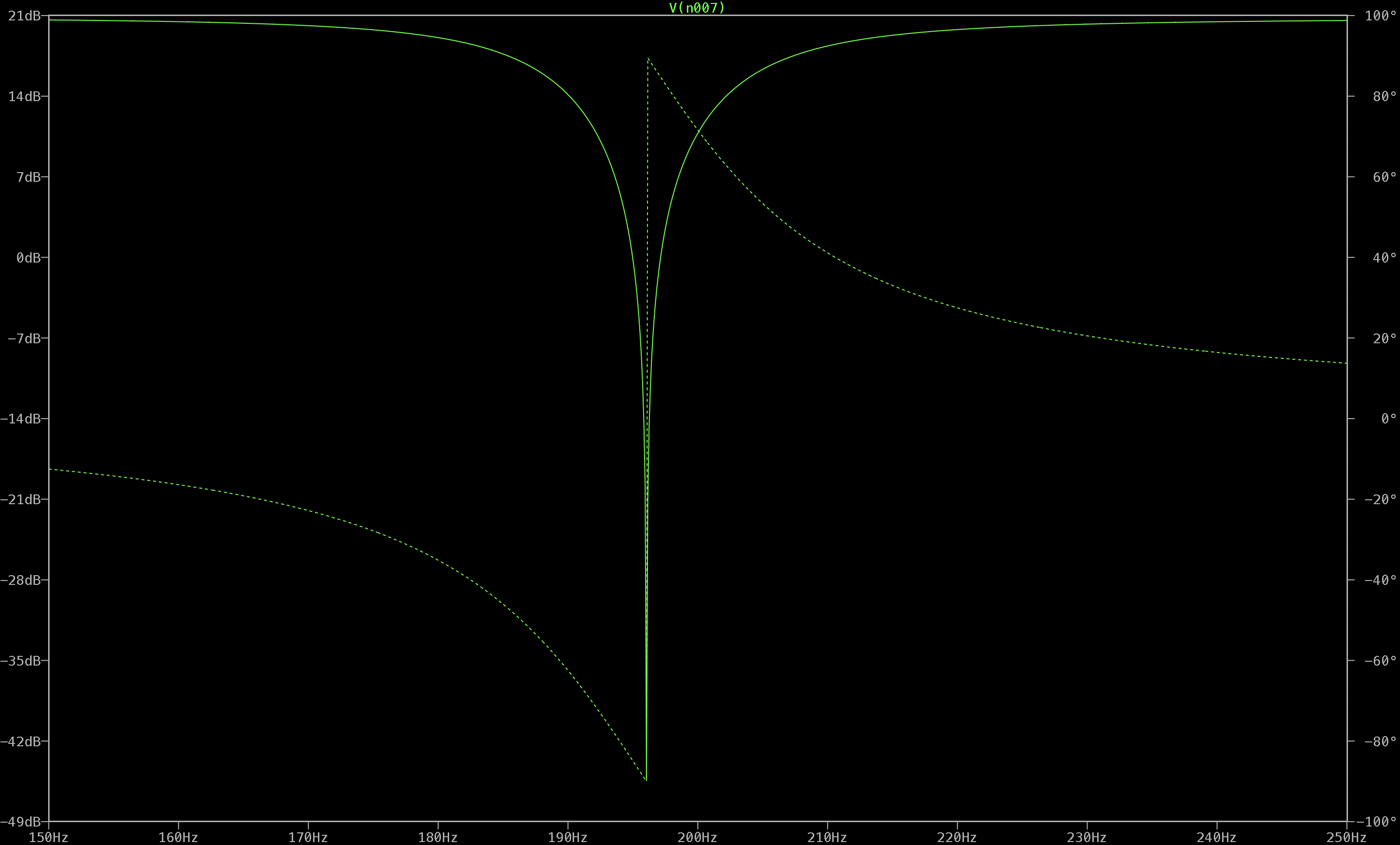
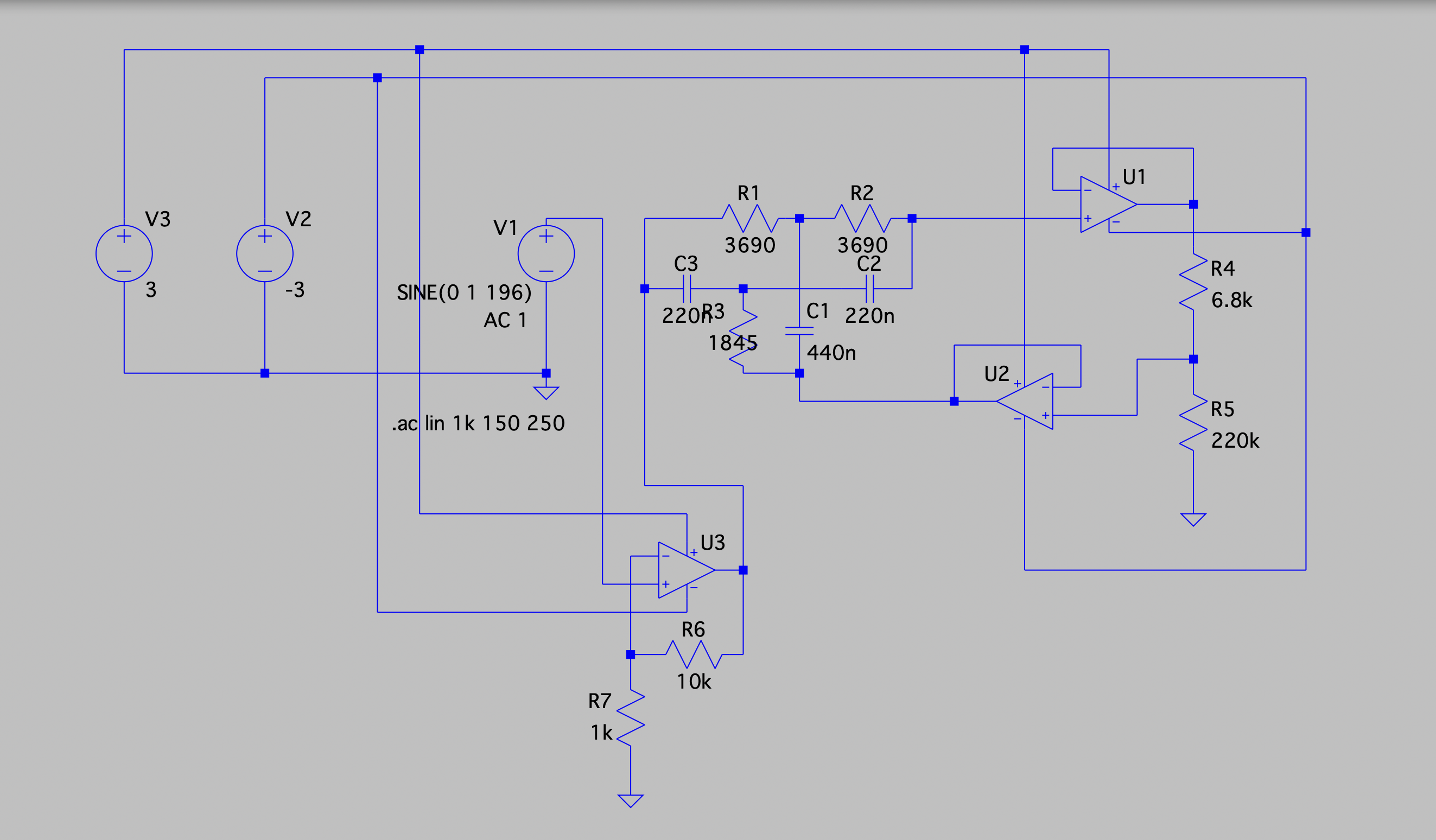
I modeled the circuit in LTspice and ran an AC sweep. This confirmed a notch at 196 Hz, as shown to the left.
PCB Design in KiCad
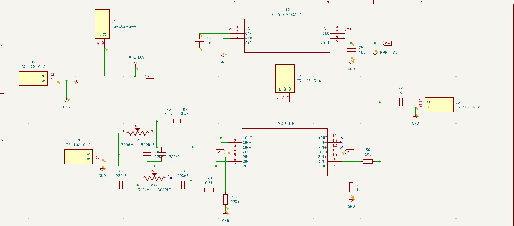
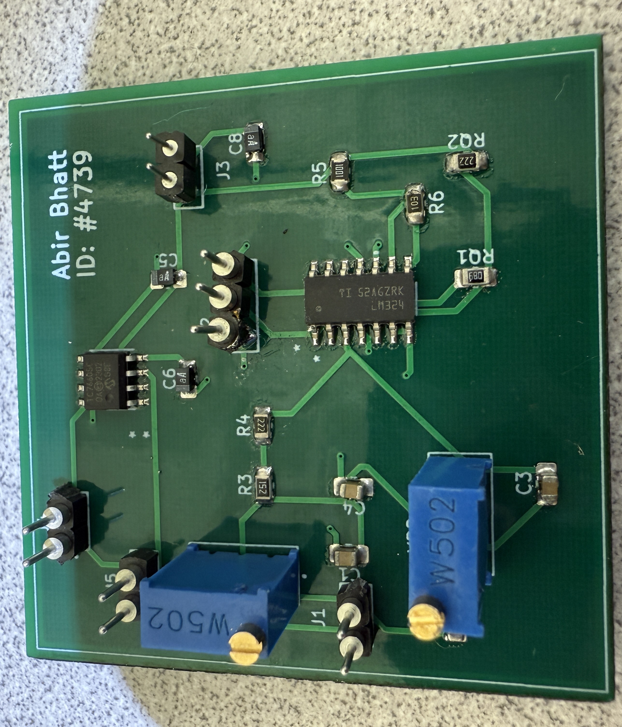
I recreated the circuit in KiCad, as shown to the right. I downloaded the missing component schematics/footprints from DigiKey. In the filter, I replaced two of the resistors with potentiometers so they could be set to exactly 3690 \(\Omega \). For the rest of the components, I used 0805 SMD hand-solder footprints, as those will be provided in the soldering process.
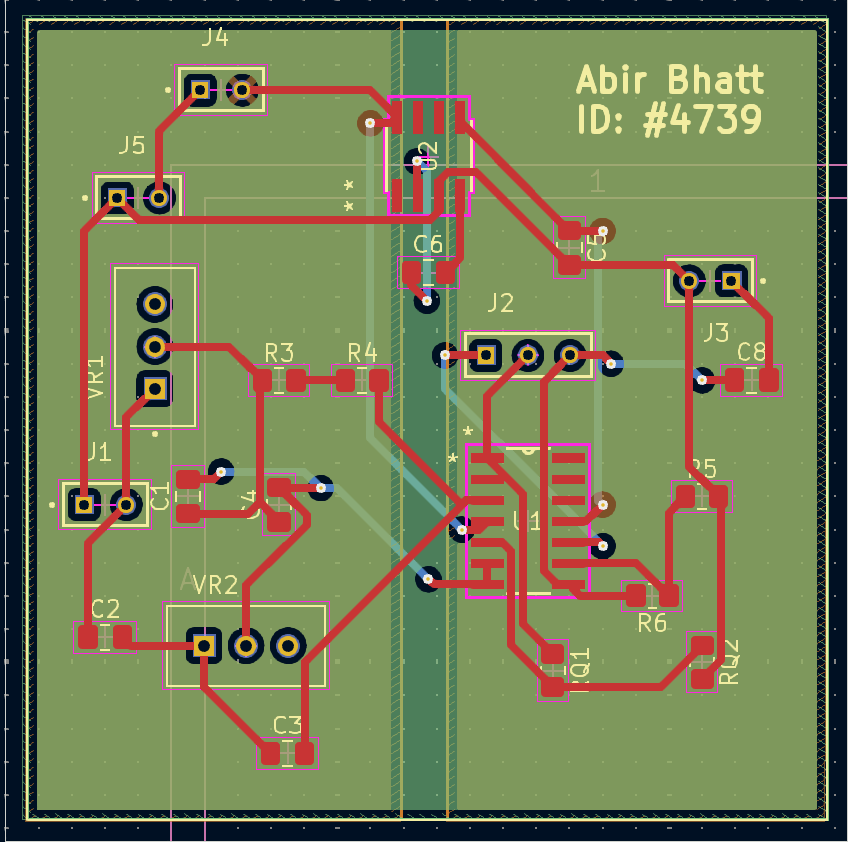
In the PCB editor, I created a four-layer board with power and ground planes. I used vias to efficiently route traces and added my name in silkscreen.
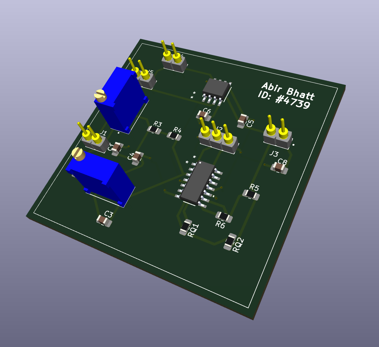
A 3D Model of the PCB is shown below.
PCB Soldering
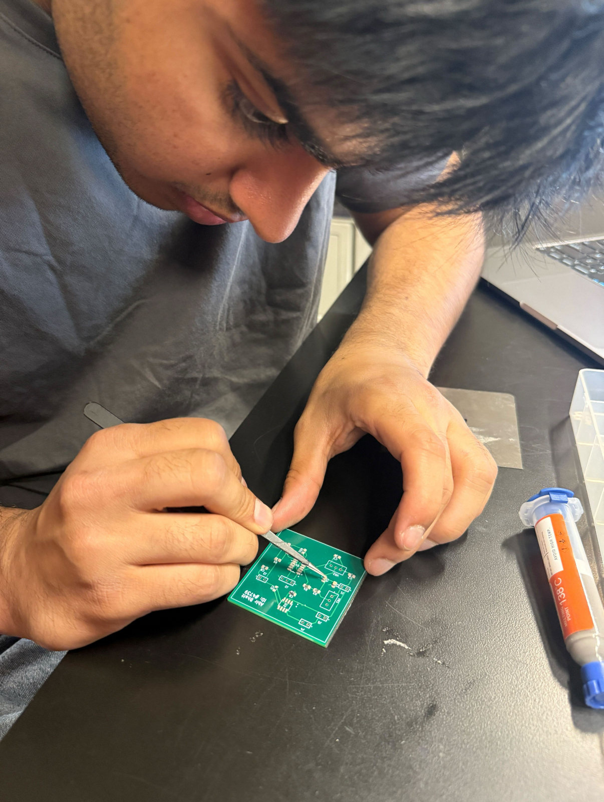
After the PCB was manufactured, I had to solder it. The ICs, capacitors, and resistors were SMD type, so I used used a stencil to spread solder paste then carefully placed each component on the board. I used a hot plate to bake the PCB. drying the solder.
The pin headers and potentiometers were THT type, so I soldered them normally using an iron.
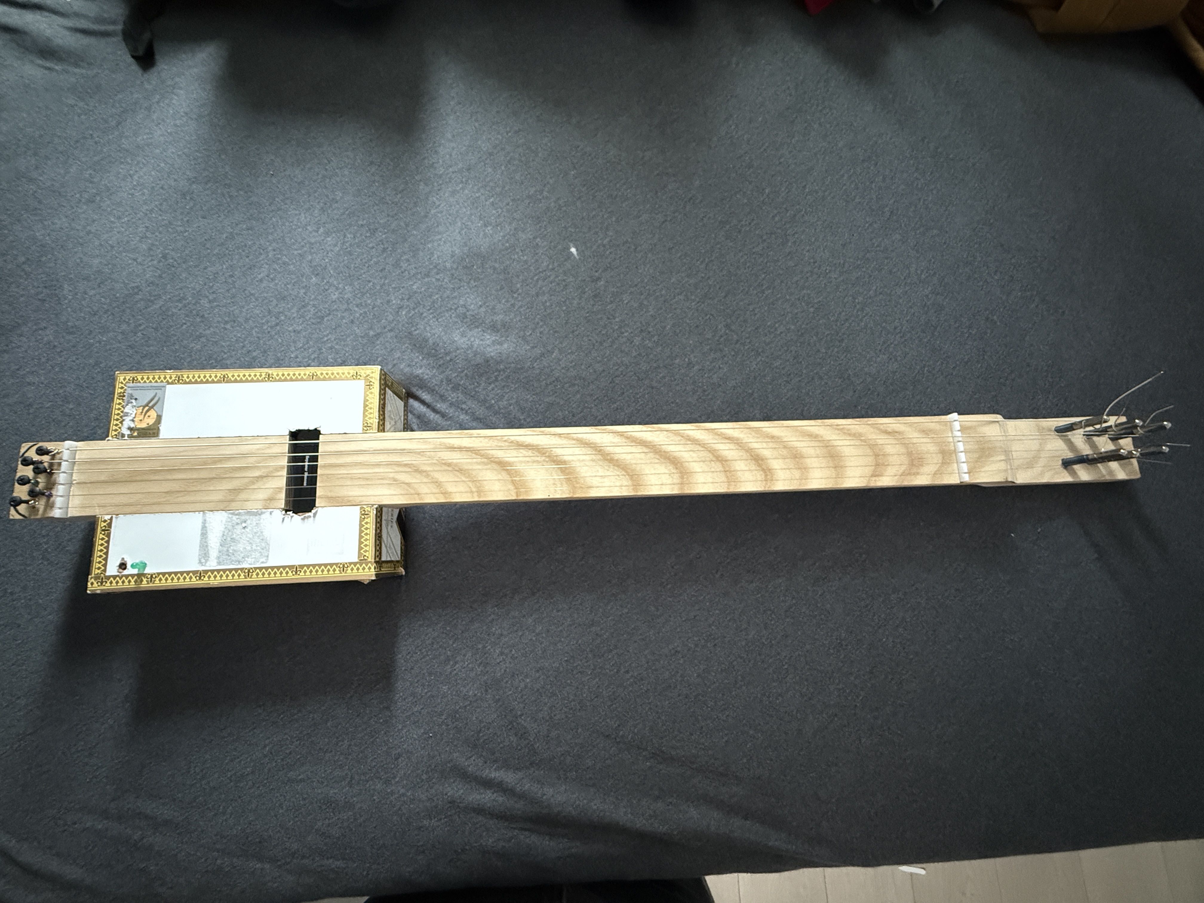
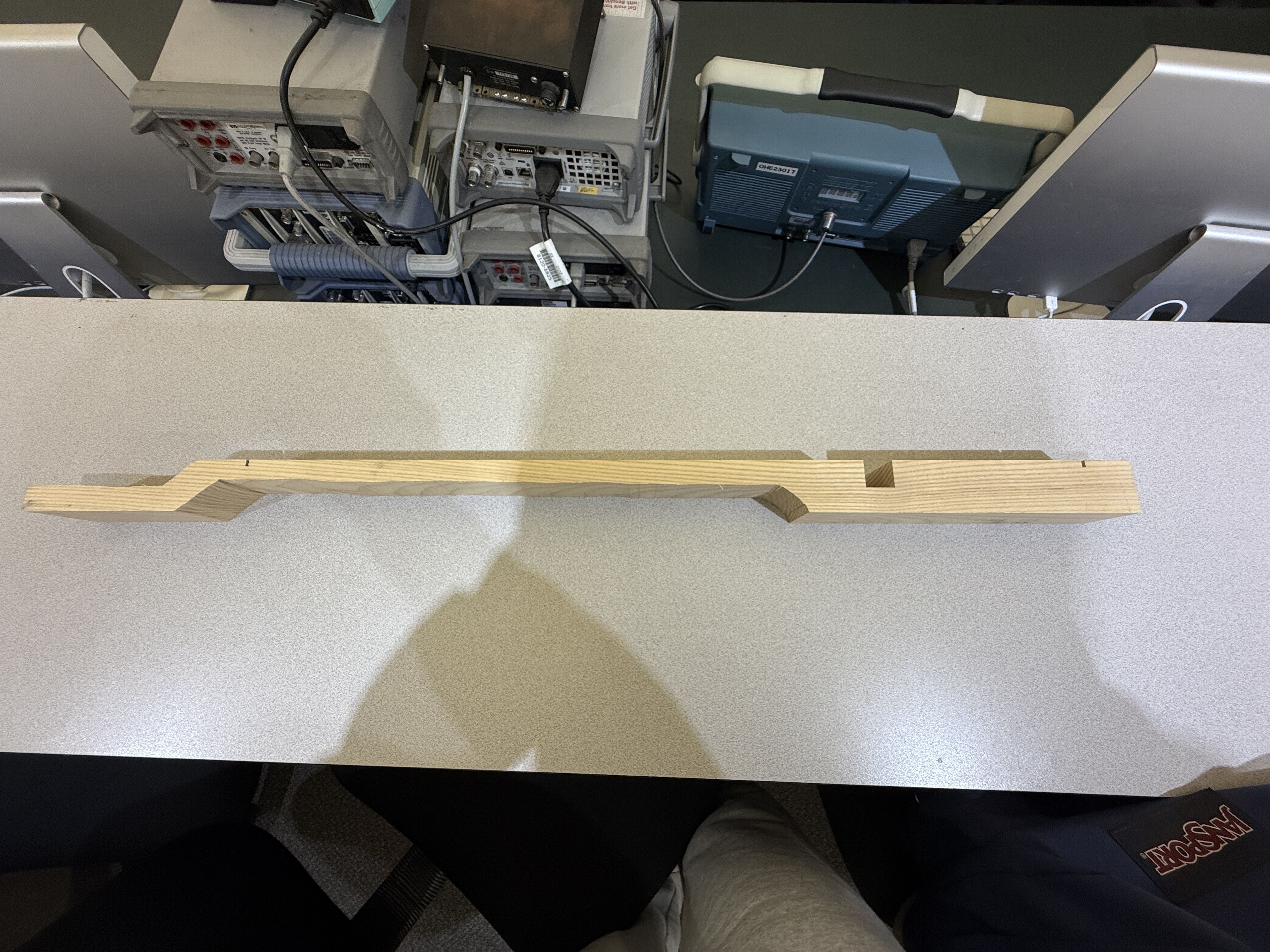
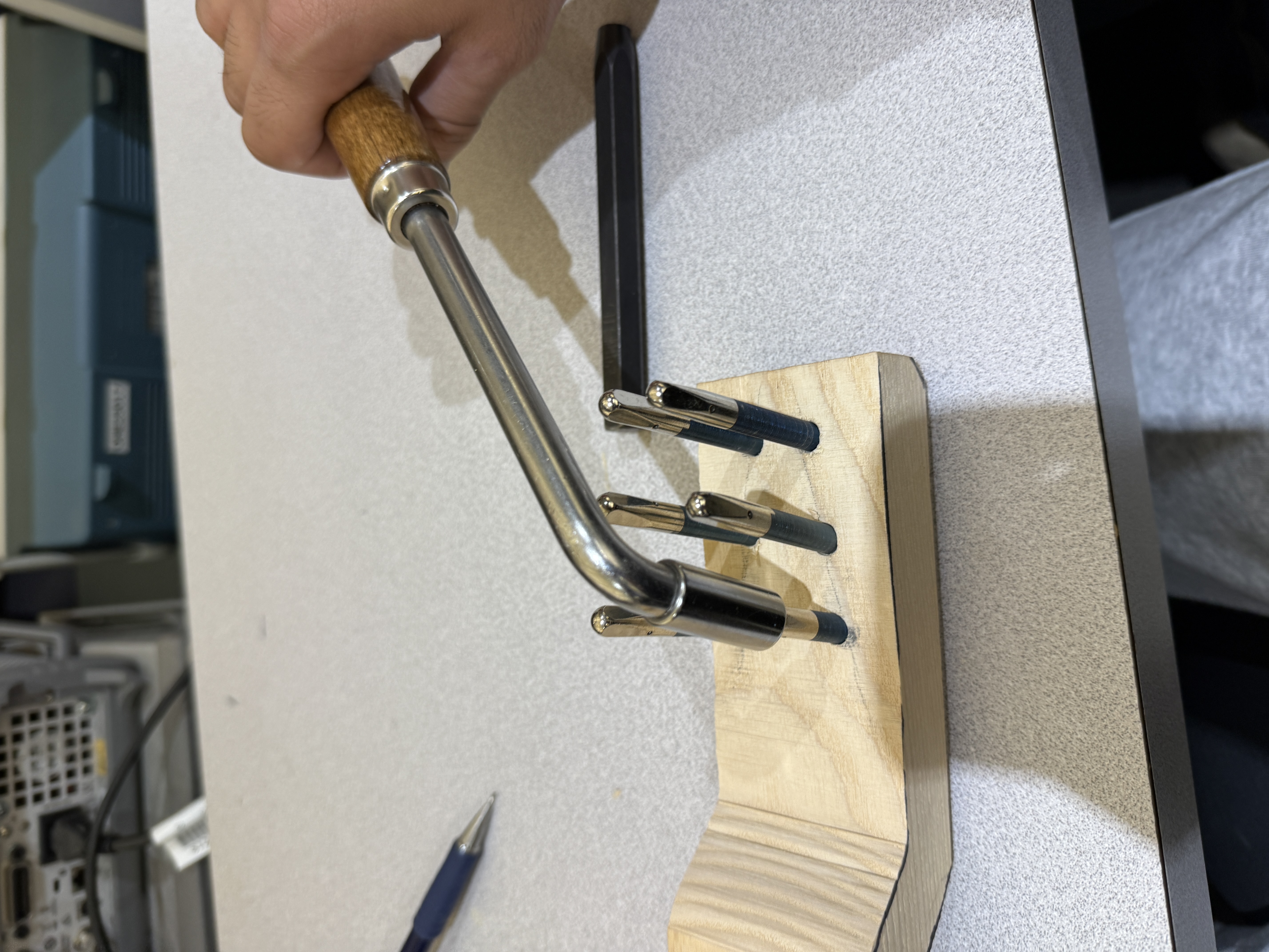
Mechanical Fabrication
I was initially given a rectangular piece of wood, but I cut and shaped it to look more like a guitar with help from the MakerSpace staff.
I also drilled six holes and hammered in piano pins.
Next Steps
I will test the PCB and integrate it with the guitar in the next week.